Autonomous Sailboat Control System using STM32

Embedded systems portfolio article · deterministic control, sensing, communication, and actuation

Full-stack embedded implementation for an autonomous sailboat platform, integrating low-level STM32 firmware, sensor acquisition, motor/servo actuation, wireless control, and power electronics into a deployable architecture.

  • STM32F103
  • Register-level firmware
  • I2C / UART / PWM
  • XBee RF
  • Power electronics

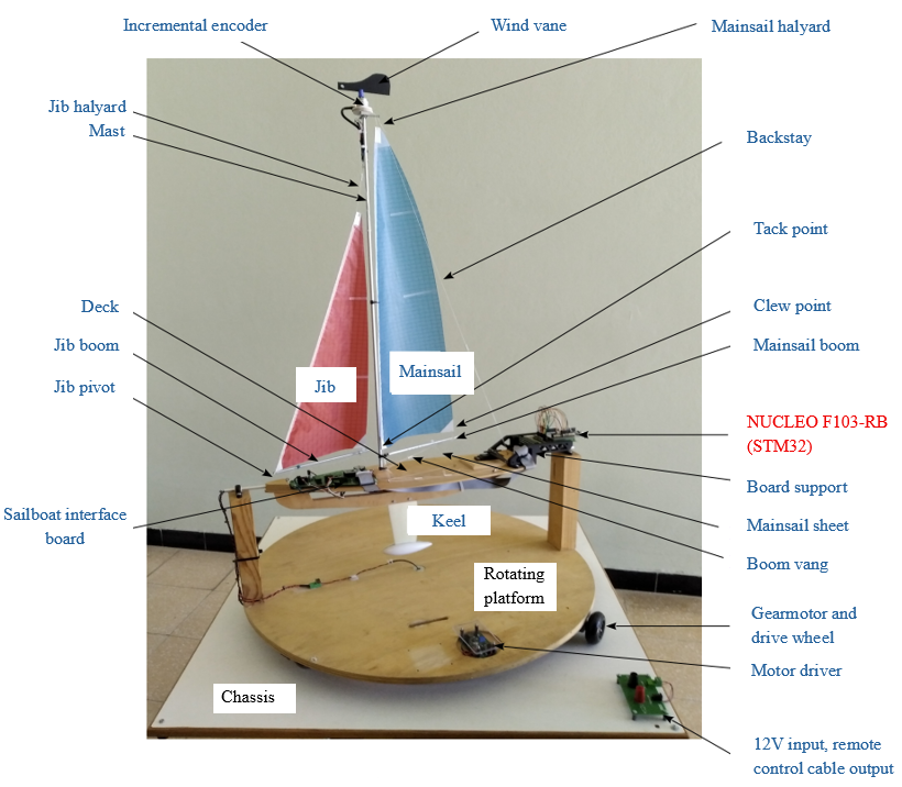
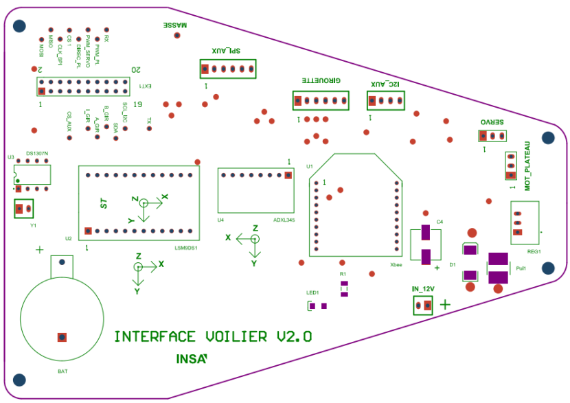
System Overview & Physical Platform

  • The mechanical platform supports full 360° yaw rotation and free roll motion under wind-induced dynamics.
  • The embedded objective is to coordinate sail trimming, controlled rotation, and remote communication on the same constrained controller.
  • The project is defined as a hardware–software integration problem where mechanical behavior and electronics are co-engineered.
Autonomous sailboat physical platform
Complete autonomous sailboat platform with embedded electronics and sensors.
NUCLEO F103-RB board
NUCLEO F103-RB board supporting the STM32F103 microcontroller.

Microcontroller Platform – STM32F103

  • The STM32F103 was selected intentionally over higher-end F4/H7 devices to enforce disciplined real-time design on limited resources.
  • Cortex-M3 core features, NVIC control, PWM-capable timers, and SPI/I2C/USART peripherals cover all mission requirements.
  • Firmware follows register-level control (no HAL abstraction) to keep timing, latency, and peripheral behavior fully deterministic.

Global Embedded Architecture

  • The system architecture integrates incremental encoder, IMU, RTC, XBee, servo actuation, motor driver, and ADC battery monitoring.
  • Each subsystem is mapped to dedicated peripherals and interrupt paths to avoid contention and non-deterministic scheduling.
  • The architecture is designed around predictable control loops rather than best-effort event handling.
Global embedded architecture diagram
Global embedded architecture of the sailboat control system.
Incremental encoder measurement principle
Wind vane and incremental encoder measurement chain.

Wind Angle Measurement (Incremental Encoder)

  • Quadrature decoding uses A/B channels plus index pulse for robust angular reference management.
  • With 360 periods and 4× decoding, the implementation improves effective resolution while preserving direction information.
  • Timer input capture and ISR-driven counting are structured for deterministic edge processing.

Roll Measurement – IMU

  • The platform compares LSM9DS1 over I2C versus ADXL345 over SPI for roll-angle estimation trade-offs.
  • Both sensor drivers were written from scratch, including multi-byte read flows and explicit bus-state handling.
  • Bus management policy prioritizes deterministic acquisition timing under concurrent peripheral activity.
IMU modules comparison
Accelerometer modules evaluated for roll angle estimation.
Servo PWM timing signal
Standard RC servo control signal (20 ms period).

Sail Trim Control – PWM Servo

  • Sail control is generated with a 20 ms period and pulse width modulation between 1 ms and 2 ms.
  • TIM PWM configuration is performed at register level to guarantee repeatable update timing.
  • Duty-cycle updates are bounded to deterministic limits to preserve stable actuator behavior.

Yaw Rotation – Motor Driver

  • Yaw actuation combines direction control with PWM switching above 20 kHz to reduce audible noise.
  • The dedicated driver board separates power and control stages for cleaner switching behavior.
  • Layout and routing decisions include EMI-aware partitioning and current-path control.
Motor driver board layout and schematic
Motor driver PCB layout and power stage schematic.
XBee wireless module
Digi XBee 2.4 GHz RF module used as wireless communication interface.

Wireless Communication – XBee

  • Communication is implemented on UART full duplex with a 100 ms command cycle.
  • Reception uses interrupt-driven framing to reduce polling overhead and latency jitter.
  • Status reporting is integrated into the same link for supervisory visibility and command acknowledgement.

Power Architecture

  • The electrical chain starts from a 12 V input with dedicated protection stage.
  • Regulation generates the 5 V domain for logic/peripherals with controlled distribution.
  • Battery telemetry uses an ADC divider ratio of 1/13 for safe measurement within converter limits.
Power input and regulation stage
12 V power input protection and regulation stage.
Custom STM32 interface PCB
Custom interface PCB integrating STM32 module and peripherals.

Interface Board

  • The STM32 board is mounted as a removable module to simplify iteration and fault isolation.
  • Debug access, oscilloscope probing points, and flexible IO breakouts are integrated from the start.
  • The interface PCB enables fast hardware validation without compromising deployment architecture.

Engineering Outcomes

  • This project represents a complete full-stack embedded implementation combining sensing, actuation, real-time control, communication protocols, and low-level firmware architecture on a constrained STM32F103 platform.
  • Firmware is structured around peripheral-level control, interrupt architecture, NVIC prioritization, and deterministic execution paths.
  • The final result integrates clock-tree control, real-time system design discipline, and hardware–software co-design into a single deployable embedded platform.

Full Technical Article (PDF)

This page is the curated narrative. The PDF contains the complete technical article, implementation details, and validation evidence.