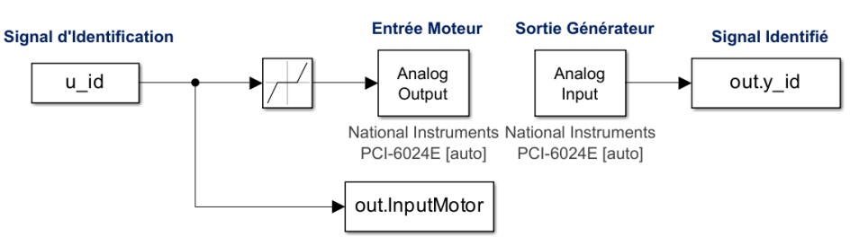
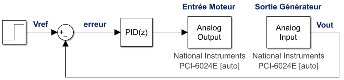
Motor–Generator System Identification and PI Control

Control Systems · System Identification · Embedded Experimentation

Full experimental identification of a real motor–generator chain, from black-box data collection to control-oriented modeling. The workflow compares excitation signals, model orders, and sampling times to retain a practical first-order plant. Design choices are driven by robustness, hardware limits, and implementation-ready control decisions.

  • System identification
  • MATLAB/Simulink
  • National Instruments
  • Frequency analysis
  • Discrete PI control

Experimental Setup

This setup implements a fully instrumented identification loop, where input excitation signals are generated in MATLAB/Simulink and applied through a National Instruments interface, while the generator output is measured in real time. This configuration enables reproducible experiments across multiple sampling rates, excitation signals, and load conditions.

Experimental setup with Simulink and NI hardware
Instrumented MATLAB/Simulink and NI setup used for repeatable identification tests.

Chirp Validation

The chirp excitation provides a smooth frequency sweep, allowing a consistent capture of the system dynamics. The identified models show good agreement in the transient regime, confirming that the dominant behavior of the motor–generator system is well represented even with low-order models.

Chirp identification validation
Chirp-based validation used to capture dominant transient dynamics.

MLBS Validation

The MLBS signal delivers the most reliable identification results, ensuring persistent excitation across the full bandwidth. This leads to the highest fit quality and reveals that a first-order model is sufficient to capture the system dynamics with strong robustness.

MLBS validation best case
MLBS case showing the most robust identification quality.

Multisine Validation

In contrast, the multisine excitation fails to properly capture the system behavior, producing poor fits and inconsistent dynamics. This highlights the strong dependency of identification quality on the excitation signal design, especially in real experimental conditions.

Multisine validation poor case
Multisine validation exposing poor fit and unstable identified behavior.

Bode Plot (Sampling Time Influence)

The frequency response remains consistent across different sampling times, indicating that the identified model is robust to discretization effects. Minor deviations at higher frequencies confirm expected limitations due to sampling and numerical approximation.

Bode plot sampling time comparison
Sampling-time sweep confirming stable frequency-domain behavior.

Identified Transfer Functions

A systematic comparison of identified transfer functions across signals, sampling times, and model orders shows that increasing model complexity does not significantly improve accuracy. A first-order model is therefore retained as the optimal trade-off between simplicity, robustness, and practical usability.

Identified transfer functions table
Cross-comparison across signals, sampling times, and model orders.

Load Influence (Oscilloscope)

The impact of load variation is directly observable on the output voltage, with clear changes in steady-state gain and transient response. This confirms that the plant dynamics are strongly dependent on the electrical load, requiring robust modeling before control design.

Oscilloscope load influence
Open-loop response showing gain and dynamic shifts under load changes.

Closed-Loop PI Architecture

The system is regulated using a discrete PI controller implemented in a closed-loop configuration. The control objective is to maintain a stable output voltage despite load variations, compensating for the absence of an integrator in the plant dynamics.

Closed-loop PI control architecture
Discrete PI loop selected to remove steady-state error.

PI Experimental Validation

Experimental results confirm that the PI controller successfully stabilizes the output voltage around the target value, even under load switching. Regulation is maintained around 9V due to hardware limits, and sensitivity to sampling time highlights practical implementation constraints.

PI controller validation oscilloscope traces
Closed-loop validation under load switching with regulation near 9V.

Full Technical Article (PDF)

This page summarizes the engineering workflow. The complete PDF includes methodology details, identified models, validation datasets, and control design evidence.

Open or Download

Access the full technical dossier in PDF format.